
After all job of building the prototype and making the sketch work, it's the time to build the circuit. It's not the objective to explain in detail how to make printed circuit boards, but only a superficial explanation about it, besides, of course, to present the project changes to make it works out of Arduino board.
Versão em português desse artigo: Volt-Amperímetro com Arduino - Parte Final: Circuito impresso.
It's a continuation of article: Arduino Volt-Ammeter - Part 1 - Breadboard
Schematic and board layout
Board designs are made with specialized softwares. There are several available, including for free. In this project I prefered to use the CadSoft Eagle given it's components library size available on the web, an interesting tip is also download the SparkFun components library that appear to have all components that they sell, a wide variety, and can save a big drawing time. The schematic is a circuit logical view that is a prerequisite for drawing the tracks and validate it later.
Basically the requirements to run an Arduino project on an independent printed circuit board is a 5v power supply, a 16Mhz crystal oscillator, and, of course, link the microcontroller pins with all digital and analog ports of Arduino board. The diagram bellow is popular on web and explain how we need to draw the schematic to work as the prototype.

The new components that are needed to be added to prototype to work in a printed circuit board are:
- 1 28 pin solder tail dip sockets (for Atmega microcontroller);
- 1 power Jack connector for PCB;
- 1 LM78L05 regulator;
- 1 1uf capacitor;
- 1 10uf capacitor;
- 1 16MHz crystal oscillator;
With the new components and microcontroller pinout, we've got the following schematic:

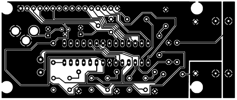
Through schematic design it's possible to validate the tracks to build from circuit layout. After putting all devices on board layout, in order to facilitate their connections, it's necessary to manually write the tracks layout, because auto-routing functions usually do not do a good job. See how the layout was designed for this project:
Building the printed circuit board
It's not the objective of this article to teach anyone to etch copper boards, for that there are several articles out there. But I'd like to make some important considerations.
The method used for this project was the heat transfer with clothes iron. I tried before to transfer the printer toner directly as explained in some articles out there. But as each printer has it's own characteristics is almost impossible determine a procedure that works in most cases, not to mention the various irons types and board sizes to be transferred. It's also notable the copper deterioration of the printed parts, which suggests that the transferred toner does not properly protect the copper during corrosion.
The solution found that worked better in this method was through Press-n-Peel paper. The blue polyester film is transferred together with the toner creating an optimal etching protection, as well as it's is removed much more easily when compared to using only toner in couche paper (or magazine paper). But make no mistake, it's not a trivial process and may also cause some waste with unsuccessful attempts. It's even recommended very careful handling with it because the blue pellicle is very delicated and any bend or scratching can remove it easily (I learned the hard way) and destroy the paper (that is not cheap).
After some damage trying to use the paper, I got a first good transfer (note that some adjustments were still needed, even minimal, with a pen):

Then, after etching:

And finally, cut and drilled:

To cut and drill the board was used a Dremel 300 rotary tool attached to Workstation. We used a 1mm drill for all holes, but note that it was not very suitable for all components and opened so much some islands eliminating almost all their contact, which complicates a lot the soldering process. In such cases it's important to use an appropriate bundle of CNC drills.
Component soldering
The component positioning at board can be properly viewed in Eagle sources. The soldered parts were arranged as following:

In order to save the board from rust it was all tinned. This procedure makes the placement of components a little complicate, because it pulls the tin, but it is important to keep the board if it has no solder mask. As you can see, the tinned visual is not the best:

Finally I arranged some cables with special connectors to help in the new device usage:

Conclusion
In closing, a short demonstration of the device working:
good job :)
ReplyDeleteI want arduino script(programme)
DeletePlz help me....
Thanks!
ReplyDeleteIt is a great work. Hats Off to you Sir.
ReplyDeleteI have a Lab Power Supply which have three different Voltages i.e. 5V, 12V and Variable
Voltage 0 to 18V. How I can interface this to my Power supply? It will be great help to complete my college projects.
What is IN and OUT terminals ?
Thanks, Harnam!! :D
ReplyDeleteTo use this device just connect the output of your power suply to the input of ammeter and then use the output of ammeter to supply power in your tests. Look at first complete PCB picture, that one with all components, in this article showing the correct position of input and output poles in screw terminals.
Don't forget the calibration!!! :P
Thanks Renato Sir !
ReplyDeleteI will build this device as soon as I get my components.
1. Will it display the current simultaneously with the voltage.
2. Can I use it for checking my Power Supply Input Voltage and Current which is 220 Volts, 50Hz. If yes, what changes I have to make.
3. Another Question I use this power supply to do my college projects. Is it possible to display the current which is normally in milliAmps?
Harman,
ReplyDelete1. It Will show simultaenously. Check it on demonstration video.
2. NOOO!! IT'S ONLY FOR DC!!!
3. The display show the current in ampere with two decimal digits.
Hope that it helps you.
Thanks! :P
Thanks Renato Sir!
ReplyDeleteI do not have words to thanks you. I am very glad that now my Lab Power Supply has its own VA meter.
How to integrate the Digital Multiple Voltage Power Supply (http://www.electronics-lab.com/projects/power/020/index.html) with this Arduino unused pins pin 2 & 7(Switches (INPUTS) S1 and S2) and Analog pins 2,3,4,& 5 as a digital pins for Output.
The source code written is for ATtiny 2313 and it is diffrent from the Arduino codes.
Regards
GOOD!!! \o/
ReplyDeleteHerman, if I properly understood, youre trying to add the voltage regulation at same board. It's a very good idea. The project of this article is good, but I would prefer to use a digital potentiometer (ex.: http://www.sparkfun.com/products/10613) to select the voltage instead of using a fixed options with resistors. It's because when you need to test a battery level sensor or a low/high voltage voltage cutoff, for example, It's better when you can to choose the voltage more precisely. And remember that analog regulators gets hot faster than we can think and they have low efficiency.
[]s :P
Hi! This is extremely useful project!! I have assembled it with LM317 voltage regulator to power a Gunn oscillator (1.25-6VDC @1A). However, I it seems to have some callibration issue. It looks like follows: If I have 2.2 Ohm resistor as a load, arduino VA meter shows 1.52/1.48V and 1.52 V on calibrating voltmeter. Now, if I disconnect the load, arduinos reading goes down to 1.37V, but calibrating voltmeters readings goes up to 2.07 V (as it should be). I guess arduino's has additional voltage drop on the shunt resistor, which in my case is 0.68 Ohm. By how much does the shunt resistor affects readings? Is it possible to have consistent readings with load and without the load?
ReplyDeleteAgain, Thank You very much!!!
Andris, it's pretty strange. Tell me more about how you built it.
ReplyDeleteMany thanks! :P
Here is how I've modified the circuit (removed buzzer and conected LM's output in the input).
ReplyDeletehttp://shareimage.org/images/ijsaxpt8tlwh50t1hxxd.png. There is something wrong with the voltage division and I can't understand why. It doesn't give proper measurement on the point between R8 and R9. It is divided by factor of around 10 (but not exactly), however voltage here increases if I connect the load in the output...
Andris, we can't predict all circuit resistence and the real R8/R9 precision, it's the reason for calibration exists. I noted that the calibration may vary with the LM78L05's input voltage, but I never seen before the measurement going down when the real input went up on input bornes. Are you ensuring a stable at least 7v for LM78L05?
ReplyDeleteOK, after some mumbo-jumbo with the bunch of wires on the breadboard I've got it to work as it is supposed! :D However, I do see the role of the shunt resistor. Either I need to calibrate meter for specific load, or voltage drop on shunt should be taken into account and summed internally to the voltage readings. I am also considering to use small resistance shunt and an opamp. But that's for later. This is my first arduino project, but it tends to be very educational. Many Thanks!!! :)
ReplyDeleteDid you improve the equation that calculate the values? Share it with us, plz! :D
ReplyDeleteRenato Sir,
ReplyDeleteYour idea about using digital potentiometer is great. I was looking for the part but it was not available in the market. It will take couple of days when it will be available with our vendor.
In the mean time, Can you guide to convert this code into Arduino sketch? How we can integrate this with this Voltage Ammeter?
Hi, Harnam. I think that you will need to capture more two buttons for UP/DOWN voltage control and send the right signal to potentiometer. It's not a big ammount of code, but you need to read the potentiometer datasheet to understand how to use it. The real problem is the amount of ports left available by ammeter. I think that all the five buttons could be handled by only one analog port.
ReplyDeleteAwesome my friend :D
ReplyDeleteRonelto Sir,
ReplyDeleteIt will take some time to get the digital potentiometer from the Vendor. In the mean time, Can we try to play around with the given circuit of http://www.electronics-lab.com/projects/power/020/index.html without integrating to the Arduino Voltmeter-Ammeter Ckt.? Switch S1 and S2 can be connected to Arduino Pin7 & Pin 2(By removing the connection of backlight of LCD from pin7 and connecting the backlight directly to the +5V of LCD through resistance, pin 7 will be free to use and Pin2 is already spare to use).
4 Analog pins (2,3,4&5)can be used as a digital
pins for 3.3V, 5V,9V and 12v outputs.
I am begineer, I don't know much about the coding. Please help in coding
//pins
Const int PIN_UP = 7;
Const int PIN_DN = 2;
Const int PIN_OUTPUT1 = 16; //Analog pin 2
Const int PIN_OUTPUT2 = 17; //Analog pin 3
Const int PIN_OUTPUT3 = 18; //Analog pin 4
Const int PIN_OUTPUT4 = 19; //Analog pin 5
void setup () {
//configure pins
pinMode (PIN_UP,INPUT);
pinMode (PIN_DN,INPUT);
pinMode (PIN_OUTPUT1, OUTPUT);
pinMode (PIN_OUTPUT2, OUTPUT);
pinMode (PIN_OUTPUT3, OUTPUT);
pinMode (PIN_OUTPUT4, OUTPUT);
How to proceed further
Harnam, hello...
ReplyDeleteLook, my name is Renato! OK? :D just kidding.. :P
To handle many buttons with only one analog port you need to assemble a set of buttons in series with resistors and then use the analogRead() to get the value. You will note that, due to the series of resistors and buttons, you will have diferent readings for each one that you push. These values are what you will need to map.
This post at Arduino forum is very explanatory: http://www.arduino.cc/cgi-bin/yabb2/YaBB.pl?num=1226896251
Try it and come back to say us if it worked.
Hi,
ReplyDeleteI need a little clarification:
the voltmeter, reads from 0 to ?
the ampere meter, reads from 0 to ?
---------
I also noticed that the ampere meter is not very precise, if instead of a resistance of 0.47 ohms, they put a smaller one, I could fix this?
thank you ;)
Voltmeter reads from 0 to 50v and the amperemeter from 0 to 10a, but may vary a bit after calibration.
ReplyDeleteIf I properly undestood the issue, the problem with precision is due to it's wide measurement range. If you look at common voltmeters, they usually have their scales divided in small ranges that you need to choose before to use and usually with only one decimal number.
thank you,
ReplyDeletehave a good work ;)
Renato Excellent work, and thank you for posting.
ReplyDeleteHow much current can this meter handle?
It will measure until 10A, but I never tested before from wich point it will start to burn.
ReplyDeleteHello Renato Sir !'
ReplyDeleteOur semester is Over and I have time to play around with Arduino and improve my Lab Power Supply. I experimented with one analog pin by connecting the 5 push buttons Btn1 (220 Ohms), Btn2 (390 Ohms), Btn3 (680 Ohms), Btn4 (2.2K), Btn2 (4.7K). One end of the button is tied to +5V and other end to ground through 1K. The output is tested by connected 5 leds. I got the following readings in the serial monitor
button 1= 838
button 2= 735
button 3= 608
button 4= 319
button 5= 177
Code:
Int led1 =3;
Int led1 =4;
Int led1 =5;
Int led1 =6;
Int led1 =7;
int sensor = A0;
Void setup() {
Serial.begin(9600);
pinMode(led1, OUTPUT);
pinMode(led2, OUTPUT);
pinMode(led3, OUTPUT);
pinMode(led4, OUTPUT);
pinMode(led5, OUTPUT);
// read the state of the analog value
void loop () {
sensorValue=analogRead(sensor);
sensorValue /=1024;
Serial.print ("\nVal#");
Serial.println (sensorValue);
if(sensorValue >=838)
{
digitalWrite(led1,HIGH);
delay (50);
} else
{
digitalWrite(led1,LOW);
delay (50);
}
if(sensorValue >=735)
{
digitalWrite(led2,HIGH);
delay (50);
} else
{
digitalWrite(led2,LOW);
delay (50);
}
if(sensorValue >=608)
{
digitalWrite(led3,HIGH);
delay (50);
} else
{
digitalWrite(led3,LOW);
delay (50);
}
if(sensorValue >=319)
{
digitalWrite(led4,HIGH);
delay (50);
} else
{
digitalWrite(led4,LOW);
delay (50);
}
if(sensorValue >=177)
{
digitalWrite(led5,HIGH);
delay (50);
} else
{
digitalWrite(led5,LOW);
delay (50);
}
}
PROBLEM:- . When the push button is pressed, led comes ON but when released it goes OFF. I failed to toggle it. Please help to resolve this issue pertaining to latch the button.
(One push ON second push to OFF)
Hmmm.. Look, LEDs will turn off at first loop after you release the button because youre using "else" without any condition inside the main loop(). To do what you want, it will need a bit more controls to handle unique clicks and LED on/off event. Remember that one simple click may affect many loop() executions.
ReplyDeleteIf you wait a bit, maybe until tomorrow, I can add this support to ebl-arduino button handler. It will permit to handle single clicks, double clicks and hold time; as it's already possible with digital ports.
Renato Sir,
ReplyDeleteHow to proceed to integrate the digital power supply as per http://www.electronics-lab.com/projects/power/020/index.html) in the same board.
By using one analog pin for controlling 5 digital
buttons ?
Is there someone who did the calculation if its possible to get 3 decimal digits with different voltage divider for 30v-3A? (http://www.electronics-lab.com/projects/power/001/index.html, upgraded version)
ReplyDeleteNice project btw, will be build =)
Very helpful post for my PCB "Printed circuit Board" Designer where they can get some ideas also.
ReplyDeleteThat's a superb post.. Thanks for step by step guide to design this type of circuit board. Like this video tutorial also.
ReplyDeleteHello
ReplyDeleteGood job.
Can you give an example of the program only on current measurements.
I need to measure the current 4-20mA
A very well done Renato, this is literally EXACTLY what I have been looking for! So thank you for taking the time to document it on your blog :D
ReplyDeleteOne quick question; I'm new to the Arduino - did you just pull the Atmega chip from the Arduino for the independent board?
Thanks again! :D
Yeah! I use Arduino only to debug the software and write the micro controller. I bought a couple of chips to work this way.
DeleteHi. Really very nice work!!. But when i tried to download the Eagle files, some FBI anti-piracy warning prevented me from doing so. Is there any other way to get these files???
ReplyDeleteThank you for your time and effort
Sorry, but all the blog's download content was hosted at megaupload and I'm not having enough time to fix it in these days. I will find another place to host everything again soon.
DeleteGreat work !!! But I was a bit disappointed when I found that your files had been removed... how does it look with your time ? Can you make them available ? Looking forward to it ... :-)
ReplyDeleteHi Renato,
ReplyDeleteGood job. I have something to ask, how can we create a instruction code to control the amount of the current flow. Example, i want to set my current limit until 1A, then if the the circuit detect the current over the limit, it will send one output instruction to energize a relay. Can you help me for the code? Urgent..
Hmm.. Sounds like good. Can you please post more details about this circuit board.
ReplyDeleteHave any of youse had any experience with any pcb assembly companies that do this?
Thank you for posting the great content…I was looking for something like this…I found it quiet interesting, hopefully you will keep posting such blogs….Keep sharing. Love your blog.
ReplyDeleteprinted circuit board fabrication
I see the files still aren't available. Can I suggest using google code to host it? http://code.google.com
ReplyDeleteHi, great project! I want to make it, but the files are uploaded on Megaupload, which is closed. Can you upload them again?
ReplyDeleteThanks,
Hello,
ReplyDeleteCongratulations on your creation.
Could you put new link to download the schematic and board?
Thank you.
Mathis
In the assembled picture I notice a transistor that is not listed in the parts list? What is the part number? NPN or PNP
ReplyDeletegreat article. The way you explained it is really awesome and makes every one to read till the end. keep posting.. pcb assembly services
ReplyDeleteDear Sir,
ReplyDeleteCould I connect the input of a variable power supply to your circuit and take the voltage from the output, for 0-10 V and 0-10 A do I understand this correctly ?
Dear Sir,
ReplyDeleteCould I connect the output of a variable power supply to the input of your circuit and take the voltage from the output of your circuit, for 0-10 V and 0-10 A, do I understand this correctly ? Also, aren't the 22pf capacitors normally going with crystals necessary ? Sorry for the double post, I made a mistake the first time.
Ted, you're right... It's useful be used together with an adjustable power supply. And you're right about the crystal capacitors as well. When I was building this project I did not have them available, but it's not really critical for this application.
ReplyDeleteDear Sir,
ReplyDeleteThanks for the answer. I made the circuit from the Eagle file provided, using your schematic without changes but with changes to PCB (added the capacitors, changed the position of components to fit a box I have).
The indication for voltage and amperage are changing continuously. For example, using 9 v from a battery on input, it goes like 12.3 , 14.8 , 18.1 when I believe (as shown in youtube video above) it should show something close to 9 volts, where I should adjust it with setup to be saved to eprom. Any idea what I might did wrong? I didn't made any changes to the program. I used an Atmega 168 with Duemillanove boot from 0.22 IDE.
Thanks again,
Ted
Ted, check your PCB for shorts that can easily occurs during etching or soldering.
DeleteDear Sir,
ReplyDeleteAfter some checking, I don't see any short. Do you have an email address in which I could send you my version of the circuit ?
Thanks, Ted.
Dear Renato,
ReplyDeleteNevermind my previous post. I saw a difference between your PCB and my version. I didn't connect the input voltage ground to the rest grounding of my PCB, as I saw was the case with your PCB. Problem solved with a piece of wire (though I don't understand really what changed with that. I am a beginner, you know...).
Thanks again for your answers, and for the Arduino Ammeter.
Ted.
Really, you provided some great information in this post. I highly acknowledge your proficient approach. I can say that you made an authentic effort. Keep sharing such great posts.
ReplyDeleteAwesome project, could you please update the download link? It gets a weird infinite redirect
ReplyDeleteDouble check it again, please! Beacause it is working for me.
DeleteHi, great project. I'm going to use it and make 2 V-A meters for my DIY PSU. My PSU is double 0-30V 3A. How much is the maximum voltage input for your Arduino Project? And also, if I put two V-A meters and I connect my PSU in dual mode +-30V will it work with the Arduino V-A meter?
ReplyDeleteThe input is regulated by a LM78L05 regulator, but when I tried to apply a 24v input it started to overheat and then to turn on and off continuously. When I say "input", it is the power that makes the circuit work, and not the power source being measured.
DeleteIt will work without problems with measuring a maximum rate of 30V and 3A, but It will not work with negative voltages due to limitations in analog to digital converter.
I see, I will power the Arduino itself on a separate 12V power supply. So the voltage divider can handle 30V for measuring? What is the limit for measuring voltage? I don't care that Arduino can't indicatge the negative voltage, but will something burn if I connect my secont PSU positive to the first PSU GND?
DeleteHello renato,
ReplyDeleteMagnificent project, very interesting, thank you for sharing it.
Could you say to me where you got yourself the resistances that you used? In particular the one that you used for the shunt (https://lh4.googleusercontent.com/_SlXk_jAXNLY/TdBMKbeKl7I/AAAAAAAAAM0/1GcSCY1521Q/placa5-legenda_en.jpg). Is it also a resistance of 1 % ? Because I do not manage to find a 0.47 ohm resistance 5W identical to your project, the one that I find are ceramic resistance (http://i.ebayimg.com/17/!By5cvU!EWk~$(KGrHqYOKjYEwtVE2y,OBMTqd,zRN!~~_35.JPG).
Thank you for the interest which you will carry in my question.
P.s: Please bear with me, I begin in electronics and also in English. Thank you.
Its not a 1% and its not critical, this one that you found looks suitable. It's possible to calibrate using another ammeter as shown in the video.
DeleteOK, but the resistance which you uses for the shunt is not one 5W?
DeleteYes, it is. The big green one.
DeleteIs it a metal film resistor(the big green one)?
DeleteThis comment has been removed by the author.
ReplyDeleteThis comment has been removed by the author.
ReplyDeleteHello, I realized a prototype of your project and it works well, thank you again.
ReplyDeleteOtherwise why do not to answer my last question?
Does not my question have any interest?
I would have wanted to know exactly which type of resistance you used in your project(1/4W, 1/8W, 1%, 5%, Metal Film, Metal Oxide, Carbon Composition...etc) that's all.
P.s: There is that the voltage which calibrates? In fact the amperage calibrates automatically according to the voltage.I am wrong?
Forget me, please. Answering here is not my main role. Moreover I have no idea about the shunt resistor chemistry, but only that it is a 5W 0.47R with 5% precision. The other ones are, if I properly remember, metal film with 1/4W and 1%.
DeleteFor calibrations you need a reliable input/output to fix the number shown in the display. The movie demonstrates how it is done. Note that if you calibrate with a 3V input, you will note a small deviation trying to measure 30V, this is why ordinary voltmeters has different scales.
A last question and I leave you,
DeleteOn my prototype during the calibration of amperes, I press on the buttons of calibration (up and down) but Nothing takes place, is it normal?(Sorry of you annoy)
Sorry for my misspelling, but my intention was to say "forgive me" instead of "forget me".
DeleteAmperes calibration takes at least five more clicks than the voltage one. The reason is that the maximum value used to map the analog port input to the real number is 10 for amperes and 50 for voltage.
No problem, those are things which arrive.
DeleteOK, everything is understandable, of the blow my prototype works well.
Thank you for having taken time to answer me.
Hello Renato,
ReplyDeleteFirst of all I thank you for sharing such a genuine work.
And I understand how much time you might have spent to build this, I truly appreciate your job.
Now my question:
I'll build this PCB again with 22pF caps along with crystal using a bit more clearance between the tracks and pads using IRON press method of making PCBs. I'm unable to understand what changes do I need to make to set the WIDE range to a bit NARROW one, since I need to measure the voltage and current from a 30V,5A(max) solar panel.
I'm trying to attach it to my solar charge controller.
Please spare some time to answer my question.
Thanks a lot again... :-)
hai sir, i need to know , to build up this VA arduino, we have to combine both part ? means part 1 and final part together ? o it is just 2 different options either we use breadboard o printer circuit board ? i have difficulty to understand .. thank in advance sir :)
ReplyDeletehello sir i am test this circuit is running but volt and amp reding in fluxchation pleas help
ReplyDeletehello sir i am test this circuit is running but volt and amp reding in fluxchation pleas help
ReplyDeletethanks for sharing such info about ampere meter
ReplyDeleteplease arduino program file shaheen814@gmail.com
ReplyDeletenice project , can u send programs file shailesh4440@gmail.com
ReplyDelete